
What is serial block-face imaging?
Serial block-face scanning electron microscopy (SBEM, SBSEM, and SBFSEM) is a way to reproducibly obtain high resolution 3D images from a sample. This method is particularly good at imaging large fields-of-view in X,Y,Z at nanometer resolution. SBEM typically relies on an in-situ ultramicrotome to be installed inside a scanning electron microscope (SEM). The SEM will collect an image of the block face, then the ultramicrotome will cut the sample to expose the next layer to be imaged, in steps as small as 15 nm.
Advantages of SBEM
| Capability | Advantage |
|---|---|
| Examines structure across orders of magnitude in scale | Maintains level of detail throughout a large dataset |
| Allows high throughput with no intervention | Useful to speed up sample analysis and reduce human error |
| Elucidates the context of observed ultrastructure | Enables you to gain more comprehensive results from one sample |
| Controls all aspects of the sectioning and acquisition process | Allows complete flexibility to optimize for a given sample |
| Eliminates section loss, damage and distortion | Avoids prohibitive processing to correct damage and distortion |
Uses
| Neuroscience | Cell biology | Material science | Other |
|---|---|---|---|
|
|
|
|
Neuroscience
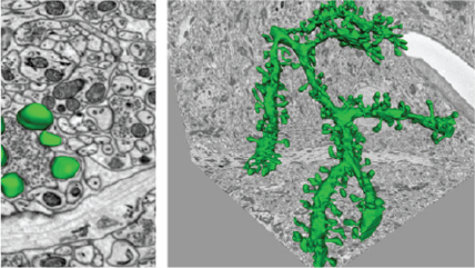
A 3D reconstruction of a dendrite from a 15,625 μm³ (25 x 25 x 25 μm) volumetric data set containing 500 serial images of mouse cerebellum generated by the 3View® system. Dendrite structure (green), buttons (yellow), and vesicles (red). Inset images, clockwise from top left: Confocal image of a dendrite; wire frame traces rendered into a volumetric model; ultra-resolution dendritic spine model with synapses; and image showing wire frame traces.

Cell biology: Complement confocal
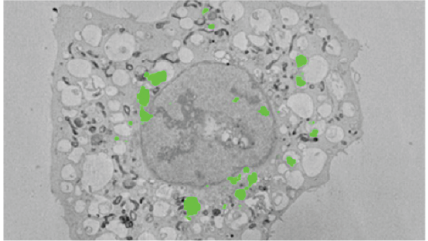
Image of HeLa cells, stably expressing LC-GFP grown on gridded glass bottom coverslips dishes, starved for 2 h in serum-free medium and cells of interest identified by confocal microscopy. The cells were then processed in situ for electron microscopy and the coverslips dissolved from the epoxy resin with hydrofluoric acid. The cells were again identified in the resin block and in subsequent serial images generated by the 3View system.

Cell biology: Developmental
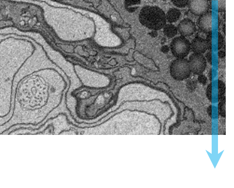
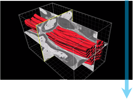
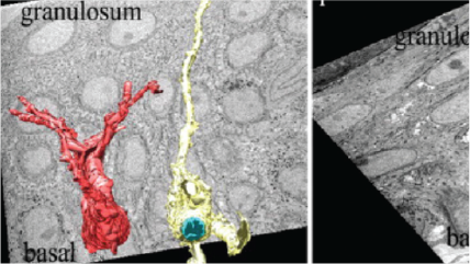
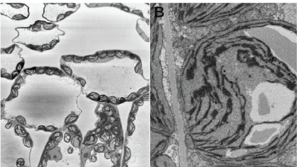
Top left: High resolution, mouse kidney, 8192 x 8192 pixel image acquired with 1.5 nm pixels. Top middle: Large field-of-view, mouse kidney, 8192 x 8192 pixel image acquired with 80 nm pixels. Right: C. elegans prepared by high pressure freezing; 4096 x 4096 pixel image acquired with 25 nm pixels. Sample courtesy of Kent McDonald, University of California, Berkeley. Bottom left: Mouse sciatic nerve, 2048 x 2048 pixel image acquired with 5 nm pixels. Bottom middle: 3D visualization of mouse sciatic nerve axons.

Material science
Upper and lower left: Images of anodized coating on aluminum surface generated by 3View system. Middle: 3D visualization of aluminum alloy with manganese particles generated by 3View system. 3D dataset contains one thousand 1024 x 1024 serial images with a pixel size of 15 nm and a cut thickness of 15 nm. 3D model created in DigitalMicrograph® using the 3D Visualization plugin.

Workflow for serial block-face imaging
3View system quick start guide
|
|
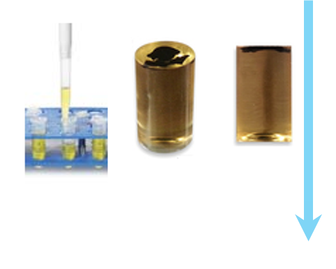
Step 1: Specimen preparation A typical biological specimen is fixed, stained with a contrasting agent and embedded in resin for stability. |
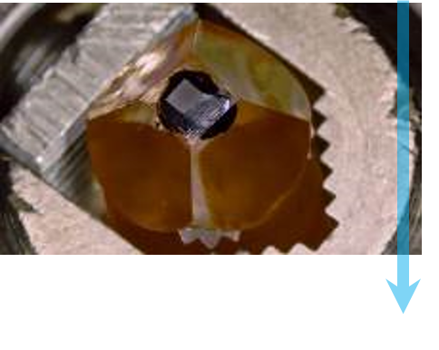 |
Step 2: Mount and transfer to SEM The specimen is trimmed to size, mounted to an aluminum pin, and optionally given a thin gold sputter coating. The specimen pin is put in the 3View system, the diamond knife is brought into contact, the door closed and evacuated. |
 |
Step 3: Optimize imaging The user selects suitable beam conditions, similar to conditions for standard SEM, but also considering effects in the Z direction. Magnification, pixel count, and dwell time are chosen such that the image has the desired resolution, field-of-view, and acquisition time. |
 |
Step 4: Automated imaging Sequential images are acquired with beam conditions of the user’s choice. Before each image, the knife removes a layer from the surface of the specimen. |
 |
Step 5: Analyze The images are stacked to form a 3D dataset, which can be processed and viewed in DigitalMicrograph® or third-party software. At this point segmentation and quantification can be performed. |

DigitalMicrograph, also known as Gatan Microscopy Suite, drives your digital cameras and surrounding components to support key applications including tomography, in-situ, spectrum and diffraction imaging, plus more.

-
 SBEM for large volume brain tissue imaging webinar
-
 Quantitative mapping of lithium in the scanning electron microscope
-
 3D visualization of an individual intact chromosome
-
 OnPoint detector minimizes charging and beam damage
-
 OnPoint increases 3View imaging speed four-fold
-
 Preserves synaptic vesicle under low kV conditions
-
 Large format image support is critical for throughput
3D-CLEM reveals that a major portion of mitotic chromosomes is not chromatin
Booth, D. G.; Beckett, A. J.; Molina, O.; Samejima, I.; Masumoto, H.; Kouprina, N.; Larionov, V.; Prior, I. A.; Earnshaw, W. C.
Holcomb, P. S.; Hoffpauir, B. K.; Hoyson, M. C.; Jackson, D. R.; Deerinck, T. J.; Marrs, G. S.; Dehoff, M.; Wu, J.; Ellisman, M. H.; Spirou, G. A.
High-throughput 3D visualization of large volumes at high resolution by 3View
Dohnalkova, A.; Kennedy, D.; Mancuso, J.; Marshall, M.; Mainwaring, P.; Fredrickson, J.
Lead asparate, an en bloc contrast stain particularly useful for ultrastructural enzymology
Walton, J.
Morphology of phagophore precursors by correlative light-electron microscopy
Gudmundsson, S. R.; Kallio, K. A.; Vihinen, H.; Jokitalo, E.; Ktistakis, N.; Eskelinen, E. L.
Tanaka, T.; Ohno, N.; Osanai, Y.; Saitoh, S.; Thai, T. Q.; Nishimura, K.; Shinjo, T.; Takemura, S.; Tatsumi, K.; Wanaka, A.
Mitochondrial morphology and function: two for the price of one!
Faitg, J.; Davey, T.; Turnbull, D. M.; White, K.; Vincent, A. E.
Ultrastructural variability of the juxtacanalicular tissue along the inner wall of Schlemm’s canal
Koudouna, E.; Young, R. D.; Overby, D. R.; Ueno, M.; Kinoshita, S.; Knupp, C.; Quantock, A. J.
Hashimoto, T.; Thompson, G. E.; Zhou, X.; Withers, P. J.
The biosynthesis of infrared-emitting quantum dots in allium fistulosum
Green, M.; Haigh, S. J.; Lewis, E. A.; Sandiford, L.; Burkitt-Gray, M.; Fleck, R.; Vizcay-Barrena, G.; Jensen, L.; Mirzai, H.; Curry, R. J.; Dailey, L. -A.
Borrett, S.; Hughes, L.
Kreshuk, A.; Walecki, R.; Koethe, U.; Gierthmuehlen, M.; Plachta, D.; Genoud, C.; Haastert-Talini, K.; Hamprecht, F. A.
Froud, K. E.; Wong, A. C. Y.; Cederholm, J. M. E.; Klugmann, M.; Sandow, S. L.; Julien, J. -P.; Ryan, A. F.; Housley, G. D.
Challenges of microtome-based serial block-face scanning electron microscopy in neuroscience
Wanner, A. A.; Kirschmann, M. A.; Genoud, C.
High-resolution whole-brain staining for electron microscopic circuit reconstruction
Mikula, S.; Denk, W.
Comparison and combination of imaging techniques for three dimensional analysis of electrical trees
Schurch, R.; Rowland, S.M.; Bradley, R.S.; Withers, P.J.
The Lowe syndrome protein OCRL1 is required for endocytosis in the zebrafish pronephric tubule
Oltrabella, F.; Pietka, G.; Ramirez, I. B.-R.; Mironov, A.; Starborg, T.; Drummond, I. A.; Hinchliffe, K. A.; Lowe, M.
Starborg, T.; Kadler, K. E.
Three-dimensional architecture of podocytes revealed by block-face scanning electron microscopy
Ichimura, K.; Miyazaki, N.; Sadayama, S.; Murata, K.; Koike, M.; Nakamura, K. -I.; Ohta, K.; Sakai, T.
Hondow, N.; Brown, M. R.; Starborg, T.; Monteith, A. G.; Brydson, R.; Summers, H. D.; Rees, P.; Brown, A.
Analysis of primary cilia in the developing mouse brain
Paridaen, J. T. M. L.; Huttner, W. B.; Wilsch-Bräuninger, M.
How to bury the dead: elimination of apoptotic hair cells from the hearing organ of the mouse
Anttonen, T.; Belevich, I.; Kirjavainen, A.; Laos, M.; Brakebusch, C.; Jokitalo, E.; Pirvola, U.
Developing 3D SEM in a broad biological context
Kremer, A.; Lippens, S.; Bartunkova, S.; Asselbergh, B.; Blanpain, C.; Fendrych, M.; Goossens, A.; Holt, M.; Janessens, S.; Krols, M.; Larsimont, J. -C.; Mc Guire, C.; Nowack, M. K.; Saelens, X.; Schertel, A.; Schepens, B.; Slezak, M.; Timmerman, V.; Theunis, C.; Van Brempt, R.; Visser, Y.; Guerin, C. J.
Application of FEA to image-based models of electrical trees with uniform conductivity
Rowland, S. M.; Schurch, R.; Pattouras, M.; Li, Q.
RBM3 mediates structural plasticity and protective effects of cooling in neurodegeneration
Peretti, D.; Bastide, A.; Radford, H.; Verity, N.; Molloy, C.; Martin, M. G.; Moreno, J. A.; Steinert, J. R.; Smith, T.; Dinsdale, D.; Willis, A. E.; Mallucci, G. R.
Pinali, C.; Holt, C. M.; Bennett, H. J.; Davenport, J. B.; Walker, R.; Murfitt, L.; Allan, L. J.; Malik, N.; Kitmitto, A.
Kempen, P. J.; Kircher, M. F.; de la Zerda, A.; Zavaleta, C. L.; Jokerst, J. V.; Mellinghoff, I. K.; Gambhir, S. S.; Sinclair, R.
Quantitative analysis of mouse pancreatic islet architecture by serial block-face SEM
Pfeifer, C. R.; Shomorony, A.; Aronova, M. A.; Zhang, G.; Cai, T.; Xu, H.; Notkins, A. L.; Leapman, R. D.
Automated analysis of spine dynamics on live CA1 pyramidal cells
Blumer, C.; Vivien, C.; Genoud, C.; Perez-Alvarez, A.; Wiegert, J. S.; Vetter, T.; Oertner, T. G.
Advanced imaging and tissue engineering of the human limbal epithelial stem cell niche
Massie, I.; Dziasko, M.; Kureshi, A.; Levis, H. J.; Morgan, L.; Neale, M.; Sheth, R.; Tovell, V. E.; Vernon, A. J.; Funderburgh, J. L.; Daniels, J. T.
Automated analysis of spine dynamics on live CA1 pyramidal cells
Blumer, C.; Vivien, C.; Genoud, G.; Perez-Alvarez, A.; Wiegert, J. S.; Vetter, T.; Oertner, T. G.
Ju, W. K.; Kim, K. Y.; Noh, Y. H.; Hoshijima, M.; Lukas, T. J.; Ellisman, M. H.; Weinreb, R. N.; Perkins, G. A.
Finite element analysis of the pressure-induced deformation of Schlemm’s canal endothelial cells
Vargas-Pinto, R.; Lai, J.; Gong, H.; Ethier, C. R.; Johnson, M.
Serial block face-scanning electron microscopy: A method to study retinal degenerative phenotypes
Mustafi, D.; Kikano, S.; Palczewski, K.
Serial block face-scanning electron microscopy: a method to study retinal degenerative phenotypes
Mustafi, D.; Kikano, S.; Palczewski, K.
Staining and embedding of human chromosomes for 3-d serial block-face scanning electron microscopy
Yusuf, M.; Chen, B.; Hashimoto, T.; Estandarte, A. K.; Thompson, G.; Robinson, I.
Three-dimensional reconstruction of skeletal muscle extracellular matrix ultrastructure
Gillies, A. R.; Bushong, E. A.; Deerinck, T. J.; Ellisman, M. H.; Lieber, R. L.
The versatile electron microscope: An ultrastructural overview of autophagy
Biazik, J.; Vihinen, H.; Anwar, T.; Jokitalo, E.; Eskelinen, E.
Mission (im)possible – mapping the brain becomes a reality
Eberle, A. L.; Selchow, O.; Thaler, M.; Zeidler, D.; Kirmse, R.
Dynein light intermediate chains maintain spindle bipolarity by functioning in centriole cohesion
Jones, L. A.; Villemant, C.; Starborg, T.; Salter, A.; Goddard, G.; Ruane, P.; Woodman, P. G.; Papalopulu, N.; Woolner, S.; Allan, V. J.
Urwyler, O.; Izadifar, A.; Dascenco, D.; Petrovic, M.; He, H.; Ayaz, D.; Kremer, A.; Lippens, S.; Baatsen, P.; Guérin, C. J.; Schmucker, D.
En bloc staining with hydroquinone treatment for block face imaging
Togo, A.; Ohta, K.; Higashi, R.; Nakamura, K.
Pinali, C.; Kitmitto, A.
Pinali, C.; Kitmitto, A.
Three dimensional imaging of electrical trees in micro and nano-filled epoxy resin
Schurch, R.; Rowland, S.M.; Bradley, R.S.; Hashimoto, T.; Thompson, G.E.; Withers, P.J.
Three dimensional imaging of electrical trees in micro and nano-filled epoxy resin
Schurch, R.; Rowland, S. M.; Bradley, R. S.; Hashimoto, T.; Thompson, G. E.; Withers, P. J.
Finite-size effects in the 3D reconstruction and morphological analysis of porous polymers
Müllner, T.; Zankel, A.; Svec, F.; Tallarek, U.
Salloum, R. H.; Chen, G.; Velet, L.; Manzoor, N. F.; Elkin, R.; Kidd, G. J.; Coughlin, J.; Yurosko, C.; Bou-Anak, S.; Azadi, S.; Gohlsch, S.; Schneider, H.; Kaltenbach, J.A.
Salloum, R. H.; Chen, G.; Velet, L.; Manzoor, N. F.; Elkin, R.; Kidd, GJ.; Coughlin, J.; Yurosko, C.; Bou-Anak, S.; Azadi, S.; Gohlsch, S.; Schneider, H.; Kaltenbach, J.A.
A quantitative three-dimensional in situ study of a short fatigue crack in a magnesium alloy
Marrow, T. J.; Mostafavi, M.; Hashimoto, T.; Thompson, G. E.
A quantitative three-dimensional in situ study of a short fatigue crack in a magnesium alloy
Marrow, T. J.; Mostafavi, M.; Hashimoto, T.; Thompson, G. E.
Rhinomonas nottbecki n. sp. (cryptomonadales) and molecular phylogeny of the family pyrenomonadaceae
Majaneva, M.; Remonen, I.; Rintala, J. M.; Belevich, I.; Kremp, A.; Setälä, O.; Jokitalo, E.; Blomster, J.
Arabidopsis NAC45/86 direct sieve element morphogenesis culminating in enucleation
Furuta, K. M.; Yadav, S. R.; Lehesranta, S.; Belevich, I.; Miyashima, S.; Heo, J.; Vatén, A.; Lindgren, O.; De Rybel, B.; Van Isterdael, G.; Somervuo, P.; Lichtenberger, R.; Rocha, R.; Thitamadee, S.; Tähtiharju, S.; Auvinen, P.; Beeckman, T.; Jokitalo, E.; Helariutta, Y.
Tsai, W. T.; Hassan, A.; Sarkar, P.; Correa, J.; Metlagel, Z.; Jorgens, D. M.; Auer, M.
Busskamp, V.; Krol, J.; Nelidova, D.; Daum, J.; Szikra, T.; Tsuda, B.; Jüttner, J.; Farrow, K.; Scherf, B. G.; Alvarez, C. P.; Genoud, C.; Sothilingam, V.; Tanimoto, N.; Stadler, M.; Seeliger, M.; Stoffel, M.; Filipowicz, W.; Roska, B.
Miyazaki, N.; Esaki, M.; Ogura, T.; Murata, K.
Miyazaki, N.; Esaki, M.; Ogura, T.; Murata, K.
Heras-Bautista, C. O.; Katsen-Globa, A.; Schloerer, N. E.; Dieluweit, S.; El Aziz OM, A.; Peinkofer, G.; Attia, W. A.; Khalil, M.; Brockmeier, K.; Hescheler, J.; Pfannkuche, K.
Differential roles of microglia and monocytes in the inflamed central nervous system
Yamasaki, R.; Lu, H.; Butovsky, O.; Ohno, N.; Rietsch, A.M.; Cialic, R.; Wu, P. M.; Doykan, C. E.; Lin, J.; Cotleur, A. C.; Kidd, G.; Zorlu, M. M.; Sun, N.; Hu, W.; Liu, L.; Lee, J. C.; Taylor, S. E.; Uehlein, L.; Dixon, D.; Gu, J.; Floruta, C. M.; Zhu, M.; Charo, I. F.; Weiner, H. L.; Ransohoff, R. M.
Mitochondrial immobilization mediated by syntaphilin facilitates survival of demyelinated axons
Ohno, N.; Chiang, H.; Mahad, D. J.; Kidd, G. J.; Liu, L.; Ransohoff, R. M.; Sheng, Z. H.; Komuro, H. Trapp, B. D.
Cooperrider, J.; Furmaga, H.; Plow, E.; Park, H. J.; Chen, Z.; Kidd, G.; Baker, K. B.; Gale, J. T.; Machado, A. G.
Hughes, A. E.; Trinchi, A.; Chen, F. F.; Yang, Y. S.; Cole, I. S.; Sellaiyan, S.; Carr, J.; Lee, P. D.; Thompson, G. E.; Xiao, T. Q.
Serial sectioning methods for 3D investigations in materials science
Zankel, A.; Wagner, J.; Poelt, P.
Lipke, E.; Hörnschemeyer, T.; Pakzad, A.; Booth, C. R.; Michalik, P.
Lipke, E.; Hörnschemeyer, T.; Pakzad, A.; Booth, C. R.; Michalik, P.
Chen, B.; Hashimoto, T.; Vergeer, F.; Burgess, A.; Thompson, G.; Robinson, I.
Pinali, C.; Bennett, H. J.; Davenport, J. B.; Caldwell, J. L.; Trafford, A. W.; Kitmitto, A.
Pinali, C.; Bennett, H. J.;Davenport, J. B.; Caldwell, J. L.; Trafford, A. W.; Kitmitto, A.
Chen, B.; Hashimoto, T.; Vergeer, F.; Burgess, A.; Thompson, G.; Robinson, I.
Transcellular degradation of axonal mitochondria
Davis, C. O.; Kim, K.; Bushong, E. A.; Mills, E. A.; Boassa, D.; Shih, T.; Kinebuchi, M.; Phan, S.; Zhou, Y.; Bihlmeyer, N. A.; Nguyen, J. V.; Jin, Y.; Ellisman, M. H.; Marsh-Armstrong, N.
Revelation of intertwining organic and inorganic fractal structures in polymer coatings
Hughes, A. E.; Trinchi, A.; Chen, F. F.; Yang, Y. S.; Cole, I. S.; Sellaiyan, S.; Carr, J.; Lee, P. D.; Thompson, G. E.; Xiao, T. Q.
Dziasko, M. A.; Armer, H. E.; Levis, H. J.; Shortt, A. J.; Tuft, S.; Daniels, J. T.
Dziasko, M. A.; Armer, H. E.; Levis, H. J.; Shortt, A. J.; Tuft, S.; Daniels, J. T.
Wu, J.; Bakerink, K. J.; Evangelista, M. E.; Thomas, G. H.
Gillies, A.; Lieber, R.
ER sheet persistence is coupled to myosin 1c–regulated dynamic actin filament arrays
Joensuu, M.; Belevich, I.; Rämö, O.; Nevzorov, I.; Vihinen, H.; Puhka, M.; Witkos, T. M.; Lowe, M.; Vartiainen, M. K.; Jokitalo, E.
Serial block face scanning electron microscopy-the future of cell ultrastructure imaging
Hughes, L.; Hawes, C.; Monteith, S.; Vaughan, S.
An enteroendocrine cell-enteric glia connection revealed by 3D electron microscopy
Bohórquez, D. V.; Samsa, L. A.; Roholt, A.; Medicetty, S.; Chandra, R.;Liddle, R. A.
Pingel, J.; Lu, Y.; Starborg, T.; Fredberg, U.; Langberg, H.; Nedergaard, A.; Weis, M.; Eyre, D.; Kjaer, M.; Kadler, K. E.
Pingel, J.; Lu, Y.; Starborg, T.; Fredberg, U.; Langberg, H.; Nedergaard, A.; Weis, M.; Eyre, D.; Kjaer, M.; Kadler, K. E.
Resolution of the three dimensional structure of components of the glomerular filtration barrier
Arkill, K. P; Qvortrup, K.; Starborg, T.; Mantell, J. M.; Knupp, C.; Michel, C. C.; Harper, S. J.; Salmon, A. H. J.; Squire, J. M.; Bates, D. O.; Neal, C. R.
Three-dimensional aspects of matrix assembly by cells in the developing cornea
Young, R. D.; Knupp, C.; Pinali, C.; Png, K. M. Y.; Ralphs, J. R.; Bushby, A. J.; Starborg,T.; Kadler, K. E.; Quantock, A. J.
Wilke, S. A.; Raam, T.; Antonios, J. K.; Bushong, E. A.; Koo, E. H.; Ellisman, M. H.; Ghosh, A.
Exploring the third dimension: Volume electron microscopy comes of age
Peddie, C. J.; Collinson, L. M.
Resolution of three dimensional structure of components of the glomerular filtration barrier
Arkill, K. P.; Qvortrup, K.; Starborg, T.; Mantell, J. M.; Knupp, C.; Michel, C. C.; Harper, S. J.; Salmon, A. H. J.; Squire, J. M.; Bates, D. O.; Neal, C. R.
Hughes, L.; Towers, K.; Starborg, T.; Gull, K.; Vaughan, S.
The protein quality control system manages plant defence compound synthesis
Pollier, J.; Moses, T.; González-Guzmán, M.; De Geyter, N.; Lippens, S.; Bossche, R. V.; Marhavý, P.; Kremer, A.; Morreel, K.; Guérin, C. J.; Tava, A.; Oleszek, W.; Thevelein, J. M.; Campos, N.; Goormachtig, S.; Goossens, A.
Nonmuscle myosin II powered transport of newly formed collagen fibrils at the plasma membrane
Kalson, N. S.; Starborg, T.; Lu, Y.; Mironov, A.; Humphries, S. M.; Holmes, D. F.; Kadler, K. E.
Widespread mitochondrial depletion via mitiphagy does not compromise necroptosis
Tait, S. W.; Oberst, A.; Quarato, G.; Milasta, S.; Haller, M.; Wang, R.; Karvela, M.; Ichim, G.; Yatim, N.; Albert, M. L.; Kidd, G.; Wakefield, R.; Frase, S.; Krautwald, S.; Linkermann, A.; Green, D. R.
Pinali, C.; Bennett, H.; Davenport, J. B.; Trafford, A. W.; Kitmitto, A.
Kuwajima, M.; Spacek, J.; Harris, K. M.
Trueman, A.; Knight, S.; Colwell, J.; Hashimoto, T.; Carr, J.; Skeldon, P.; Thompson, G.
Connectomic reconstruction of the inner plexiform layer in the mouse retina
Helmstaedter, M.; Briggman, K. L.; Turaga, S. C.; Jain, V.; Seung, H. S.; Denk, W.
Hashimoto, T.; Thompson, G. E.; Curioni, M.; Zhou, X. R.; Skeldon, P.
Dwyer, L.; Robson, J.; da Fonseca, J. Q.; Kamp, N.; Hashimoto, T.; Thompson, G. E.
Construction of a polarized neuron
Holcomb, P. S.; Deerinck, T. J.; Ellisman, M. H.; Spirou, G. A.
Three dimensional electron microscopy of cellular organelles by serial block face SEM and ET
Vihinen, H.; Belevich, I.; Jokitalo, E.
Wong, J.; Baddeley, D.; Bushong, E. A.; Yu, Z.; Ellisman, M. H.; Hoshijima, M.; Soeller, C.
Functional development of the olfactory system in zebrafish
Miyasaka, N.; Wanner, A. A.; Li, J.; Mack-Bucher, J.; Genoud, C.; Yoshihara, Y.; Friedrich, R. W.
BMP signaling specifies the development of a large and fast CNS synapse
Xiao, L.; Michalski, N.; Kronander, E.; Gjoni, E.; Genoud, C.; Knott, G.; Schneggenburger, R.
DP2: Distributed 3D image segmentation using micro-labor workforce
Giuly, R. J.; Kim, K. Y.; Ellisman, M. H.
Shigetomi, E.; Bushong, E. A.; Haustein, M. D.; Tong, X.; Jackson-Weaver, O.; Kracun, S.; Xu, J.; Sofroniew, M. V.; Ellisman, M. H.; Khakh, B. S.
Analyzing the structure and function of neuronal circuits in zebrafish
Friedrich, R. W.; Genoud, C.; Wanner, A. A.
WDR81 is necessary for purkinje and photoreceptor cell survival
Traka, M.; Millen, K. J.; Collins, D.; Elbaz, B.; Kidd, G. J.; Gomez, C. M.; Popko, B.
Large-scale automatic reconstruction of neuronal processes from electron microscopy images
Kaynig, V.; Vazquez-Reina, A.; Knowles-Barley, S.; Roberts, M.; Jones, T. R.; Kasthuri, N.; Miller, E.; Lichtman, J.; Pfister, H.
Boassa, D.; Berlanga, M. L.; Yang, M. A.; Terada, M.; Hu, J.; Bushong, E. A.; Hwang, M.; Masliah, E.; George, J. M.; Ellisman, M. H.
Revealing the three dimensional internal structure of aluminium alloys
Thompson, G. E.; Hashimoto, T.; Zhong, X. L.; Curioni, M.; Zhou, X.; Skeldon, P.; Withers, P. J.; Carr, J. A.; Monteith, A. G.
Jurrus, E.; Watanabe, S.; Giuly, R. J.; Paiva, A. R.; Ellisman, M. H.; Jorgensen, E. M.; Tasdizen, T.
Wilke, S. A.; Antonios, J. K.; Bushong, E. A.; Badkoobehi, A.; Malek, E.; Hwang, M.; Terada, M.; Ellisman, M. H.; Ghosh, A.
Autosomal recessive retinitis pigmentosa E150K opsin mice exhibit photoreceptor disorganization
Zhang, N.; Kolesnikov, A. V.; Jastrzebska, B.; Mustafi, D.; Sawada, O.; Maeda, T.; Genoud, C.; Engel, A.; Kefalov, V. J.; Palczewski, K.
Starborg, T.; Kalson, N. S.; Lu, Y.; Mironov, A.; Cootes, T. F.; Holmes, D. F.; Kadler, K. E.
Paridaen, J. T. M. L.; Wilsch-Bräuninger, M.; Huttneremail, W. B.
Three-dimensional structure analysis and percolation properties of a barrier marine coating
Chen, B.; Guizar-Sicairos,M.; Xiong,G.; Shemilt, L.; Diaz, A.; Nutter, J.; Burdet,N.; Huo,S.; Mancuso, J.; Monteith,A.; Vergeer,F.; Burgess,A.; Robinson, I.
Anttonen, T.; Kirjavainen, A.; Belevich, I.; Laos, M.; Richardson, W. D.; Jokitalo, E.; Brakebusch, C.; Pirvola, U.
Müllner, T.; Zankel, A.; Mayrhofer, C.; Reingruber, H.; Höltzel, A.; Lv, Y.; Svec, F.; Tallarek, U.
Investigation of dealloying by ultra-high-resolution nanotomography
Hashimoto, T.; Curioni, M.; Zhou, X.; Mancuso, J.; Skeldon, P.; Thompson, G. E.
Schwartz, C. L.; Heumann, J. M.; Dawson, S. C.; Hoenger,A.
Prdm3 and Prdm16 are H3K9me1 methyltransferases required for mammalian heterochromatin integrity
Pinheiro, I.; Margueron, R.; Shukeir, N.; Eisold, M.; Fritzsch, C.; Richter, F. M.; Mittler, G.; Genoud, C.; Goyama, S.; Kurokawa, M.; Son, J.; Reinberg, D.; Lachner, M.; Jenuwein, T.
Puhka, M.; Joensuu, M.; Vihinen, H.; Belevich, I.; Jokitalo, E.
Zhuravleva, E.; Gut, H.; Hynx, D.; Marcellin, D.; Bleck, C. K.; Genoud, C.; Cron, P.; Keusch, J. J.; Dummler, B.; Esposti, M. D.; Hemmings, B. A.
Azeloglu, E.; Stothers, M.; Deerinck, T. J.; Falkenberg, C.; Chen, Y.; He, J. C.; Hone, J. C.; Leslie, L. M.; Ellisman, M. H.; Iyengar, R.
Extrusion of misfolded and aggregated proteins--a protective strategy of aging neurons?
Doehner, J.; Genoud, C.; Imhof, C.; Krstic, D.; Knuesel, I.
3D segmentation of SBFSEM images of neuropil by a graphic model over supervoxel boundaries
Andres, B.; Koethe, U.; Kroeger, T.; Helmstaedter, M.; Briggman, K. L.; Denk, W.; Hamprecht, F. A.
Differential modulation of retinal degeneration by Ccl2 and Cx3cr1 chemokine signalling
Luhmann, U. F.; Lange, C. A.; Robbie, S.; Munro, P. M.; Cowing, J. A.; Armer, H. E.; Luong, V.; Carvalho, L. S.; MacLaren, R. E.; Fitzke, F. W.; Bainbridge, J.W.; Ali, R. R.
Beam deceleration for block-face scanning electron microscopy of embedded biological tissue
Ohta, K.; Sadayama, S.; Togo, A.; Higashi, R.; Tanoue, R.; Nakamura, K.
Multivesicular exocytosis in rat pancreatic beta cells
Hoppa, M. B.; Jones, E.; Karanauskaite, J.; Ramracheya, R.; Braun, M.; Collins, S. C.; Zhang, Q.; Clark, A.; Eliasson, L.; Genoud, C.; Macdonald, P. E.; Monteith, A. G.; Barg, S.; Galvanovskis, J.; Rorsman, P.
Structural neurobiology: Missing link to a mechanistic understanding of neural computation
Denk, W.; Briggman, K. L.; Helmstaedter, M.
Giuly, R. J.; Martone, M. E.; Ellisman, M. H.
Volume electron microscopy for neuronal circuit reconstruction
Briggman, K. L.; Bock, D. D.
Yan, J.; Walker, C. G.; O'sullivan, M. J.; Bushong, E. A.; Ellisman, M. H.; Hoshijima, M.; Rajagopal, V.
High contrast en bloc staining of neuronal tissue for field emission scanning electron microscopy
Tapia, J. C.; Kasthuri, N.; Hayworth, K. J.; Schalek, R.; Lichtman, J. W.; Smith, S. J.; Buchanan, J.
Ou, H. D.; Kwiatkowski, W.; Deerinck, T. J.; Noske, A.; Blain, K. Y.; Land, H. S.; Soria, C.; Powers, C. J.; May, A. P.; Shu, X.; Tsien, R. Y.; Fitzpatrick, J. A. J.; Long, J. A.; Ellisman, M. H.; Choe, S.; O'Sheaemail, C. C.
Modern electron microscopy methods for C. elegans
Hall, D. H.; Hartwieg, E.; Nguyen, K. C.
Mustafi, D.; Kevany, B. M.; Genoud, C.; Okano, K.; Cideciyan, A. V.; Sumaroka, A.; Roman, A. J.; Jacobson, S. G.; Engel, A.; Adams, M. D.; Palczewski, K.
Motskin, M.; Müller, K. H.; Genoud, C.; Monteith, A. G.; Skepper, J. N.
Fast extraction of neuron morphologies from large-scale SBFSEM image stacks
Lang, S.; Drouvelis, P.; Tafaj, E.; Bastian, P.; Sakmann, B.
Kalson, N. S.; Holmes, D. F.; Herchenhan, A.; Lu, Y.; Starborg, T.; Kadler, K. E.
Wong, J. I. S.; Baddeley, D.; Bushong, E. A.; Ellisman, M.; Hoshijima, M.; Soeller, C.
Mun, J. Y.; Jeong, S. Y.; Kim, J. H.; Han, S. S.; Kim, I. H.
Basement membrane changes in capillaries of the ageing human retina
Powner, M. B.; Scott, A.; Zhu, M.; Munro, P. M.; Foss, A. J.; Hageman, G. S.; Gillies, M. C.; Fruttiger, M.
Cadherin-9 regulates synapse-specific differentiation in the developing hippocampus
Williams, M. E.; Wilke, S. A.; Daggett, A.; Davis, E.; Otto, S.; Ravi, D.; Ripley, B.; Bushong, E. A.; Ellisman, M. H.; Klein, G.; Ghosh, A.
High-accuracy neurite reconstruction for high-throughput neuroanatomy
Helmstaedter, M.; Briggman, K. L.; Denk, W.
Role of elastin anisotropy in structural strain energy functions of arterial tissue
Rezakhaniha, R.; Fonck, E.; Genoud, C.; Stergiopulos, N.
Modeling of flow in a polymeric chromatographic monolith
Koku, H.; Maier, R. S.; Czymmek, K. J.; Schure, M. R.; Lenhoff, A. M.
Quantitative Characterisation of microfiltration membranes by 3D reconstruction
Reingruber, H.; Zankel, A.; Mayrhofer, C.; Poelt, P.
Shu, X.; Lev-Ram, V.; Deerinck, T. J.; Qi, T.; Ramko, E. B.; Davidson, M. W.; Jin, Y. Ellisman, M. H.; Tsien, R. Y.
Wiring specificity in the direction-selectivity circuit of the retina
Briggman, K. L.; Helmstaedter, M.; Denk, W.
Nguyen, J. V.; Soto, I.; Kim, K.; Bushong, E. A.; Oglesby, E.; Valiente-Soriano, F. J.; Yang, Z.; Davis, C. O.; Bedont, J. L.; Son, J. L.; Wei, J. O.; Buchman, V. L.; Zack, D. J.; Vidal-Sanz, M.; Ellisman, M. H.; Marsh-Armstrong, N.
Environmental scanning electron microscopy (ESEM)--a versatile tool in studying plants.
Stabentheiner, E.; Zankel A.; Pölt P.
Jurrus, E.; Paiva, A. R.; Watanabe, S.; Anderson, J. R.; Jones, B. W.; Whitaker, R. T.; Jorgensen, E. M.; Marc, R. E.; Tasdizen, T.
Reconstruction of a neuron from SBFSEM: tools, reliability, accuracy and efficiency
Drouvelis, P.; Kurz, T.; Bastian, P.; Sakmann, B.; Lang, S.
Deerinck, T. J.; Bushong, E. A.; Lev-Ram, V.; Shu, X.; Tsien, R. Y.; Ellisman, M. H.
Structure-function studies of blood and air capillaries in chicken lung using 3D electron microscopy
West, J. B.; Fu, Z.; Deerinck, T. J.; Mackey, M. R.; Obayashi, J. T.; Ellisman, M.H.
Imaging transient blood vessel fusion events in zebrafish by correlative volume electron microscopy
Armer, H. E. J.; Mariggi, G.; Png, K. M. Y.; Genoud, C.; Monteith, A. G.; Bushby, A. J.; Gerhardt, H.; Collinson, L. M.
Saetzler, K.; McCanny, P.; Rodriguez, E.P.; Horstmann, H.; Bruno, R.M.; Denk, W.
Axon tracking in serial block-face scanning electron microscopy
Jurrus, E.; Hardy, M.; Tasdizen, T.; Fletcher, P. T.; Koshevoy, P.; Chien, C. B.; Denk, W.; Whitaker, R.
Mishchenko, Y.
Three-dimensional reconstruction methods for Caenorhabditis elegans ultrastructure
Müller-Reichert, T.; Mancuso, J.; Lich, B.; McDonald, K.
Ultramicrotomy in the ESEM, a versatile method for materials and life sciences
Zankel, A.; Kraus, B.; Poelt, P.; Schaffer, M.; Ingolic, E.
Genoud, C.; Mancuso, J.; Monteith, S.; Kraus, B.
Contour-propagation algorithms for semi-automated reconstruction of neural processes
Macke, J. H.; Maack, N.; Gupta, R.; Denk, W.; Schölkopf, B.; Borst, A.
Segmentation of SBFSEM volume data of neural tissue by hierarchical classification
Andres, B.; Köthe, U.; Helmstaedter, M.; Denk, W.; Hamprecht, F. A.
Alpha-herpesvirus infection induces the formation of nuclear actin filaments
Feierbach, B.; Piccinotti, S.; Bisher, M.; Denk, W.; Enquist, L. W.
Serial block-face scanning electron microscopy to reconstruct three-dimensional tissue nanostructure
Denk, W.; Horstmann, H.
Applications
|
|
|
|
|
Optimizing three-dimensional electron microscopy results at low kV |
Protocols
3View recipes
3View quick start guide
3View diamond knife cleaning procedure
NCMIR methods for 3D EM: A new protocol for preparation of biological specimens for serial block-face scanning electron microscopy
OTO fixation for SEM and block-face imaging
Using transmission electron microscopy and 3View to determine collagen fibril size and three-dimensional organization (Nature video)